| Understanding the Internet Protocol 32-Bit Address | |
| Classes of IP Addresses | |
| Address Resolution Overview | |
| Configuring TCP/IP on NT Server 4.0 | |
| Testing Configuration |
In order for your computer to communicate using TCP/IP it must have a way of identifying itself as a unique entity on the network. It does this by using a 32-bit address. In the first sections of this chapter we will dissect the 32-bit address and see how IP addresses are broken down into different classes. In the third section we will investigate how an Internet Protocol address is resolved and converted into a hardware address. In the fourth section you will learn how to configure TCP/IP on your Windows NT Server. Finally, I will show you how to use a couple of different utilities to test your TCP/IP configuration.
The TCP/IP suite consists of several different protocols and the 32-bit address relates to the Internet Protocol (IP). In this section we will see how the 32-bit IP address is separated into a network portion and a host portion by using a subnet mask.
Just as a street address identifies a house located in your town, an IP address
uniquely identifies a system located on your network . Figure 3-1 shows some examples of
32-bit IP addresses. 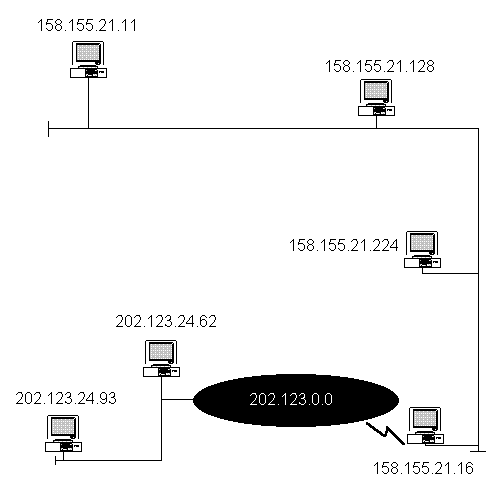
Figure 1 32-Bit IP Addresses
As you see in Figure 3-1, each computer system is identified by a unique set of numbers, which are broken down into four separate octets. An octet is a unit of data that is 8 bits in length. It works like this: if you take the four octets and multiply them by 8 bits you will arrive at the 32-bit address. The two common methods of displaying the four octets are binary format and dotted-decimal notation.
The binary representation of a 32-bit address is broken down into four
groups of binary digits as shown in Figure 3-2. Although your computer system operates
on binary, it would be difficult for us humans to remember binary representations of IP
addresses. Imagine if you asked a coworker what his IP address was and he said, in
machine-gun speed, "00001010 00000001 11100000 01100000." 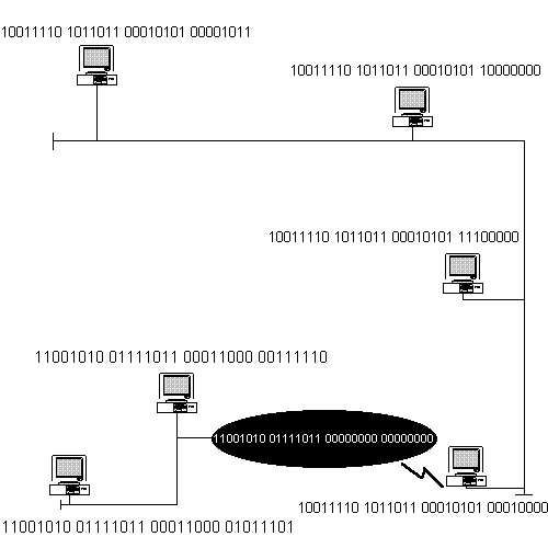
Figure 2 Binary Address Representations
Because it is too cumbersome for humans to communicate IP addresses in a binary format, dotted-decimal representation is commonly used. Dotted-decimal consists of four 8-bit fields written in base 10 with dots (periods) separating the fields. Each 8-bit field is represented by a number ranging from 0 to 255. Figure 3-3 compares dotted decimal-representation to the equivalent binary representation.
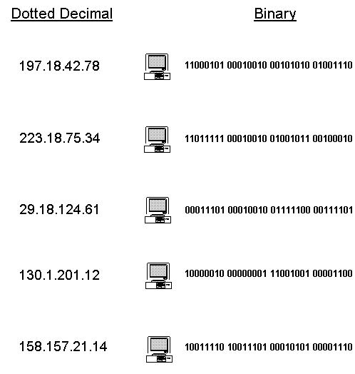
Figure 3 Dotted-Decimal and Binary Representation
Converting an address from dotted-decimal to binary is actually a very easy process. Each of the eight bits can be in either a 1 or 0 condition. The place occupied by the 1 in the 8 bits dictates its value. The Most Significant Bit (MSB) is at the far left of the octet while the Least Significant Bit (LSB) is at the far right of the octet. Figure 3-4 shows the values for the different placeholders starting with the MSB and also show examples of converting from binary to decimal and decimal to binary.
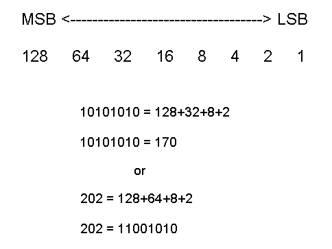
Figure 4 Binary to Decimal and Decimal to Binary Conversion
The network ID is the portion of the 32-bit IP address that identifies which network a particular system is on. It is determined by performing an AND operation of the subnet mask and the IP address. The AND operation is a function of Boolean algebra. Subnet masks will be covered later in the chapter.
The Internet Network Information Center (InterNIC) is the agency responsible for issuing all network IDs that will be used on the Internet. InterNIC operates under contract from the National Science Foundation (NSF) as the central authority for assigning the network ID portion of the IP address. This ensures that all addresses used on the Internet are unique and conflicts will not occur. The size of your organization dictates which network ID the InterNIC will issue to you. Later in this chapter you will see the different network IDs that are available.
The InterNIC assigns a network ID only for Internet IP addresses. An Intranet ID is assigned by your Network Manager. However, there are three address ranges set aside for systems not connected to the Internet (RFC 1597):
| 10.0.0.0 through 10.255.255.255 | |
| 172.16.0.0 through 172.31.255.255 | |
| 192.168.0.0 through 192.168.255.255 |
It is not wise to use an IP address from these reserved ranges because you may run into complications if you ever decide to put your network on the Internet. To connect your systems to the Internet, file the appropriate paperwork with the InterNIC and obtain your own unique network ID.
Host IDs must be unique to the local network ID. When you assign valid host IDs, there are no rules in making the assignments. Many network administrators over the years have opted to use groups in handing out host IDs in order to easily identify the host.
The practice has been to assign host IDs in groups based on host type and give routers the lowest range; for example
w.x.y.1 through w.x.y.25 Routers
w.x.200.1 through w.x.200.254 NT servers
w.x.240.1 through w.x.240.254 UNIX hosts
Microsoft strongly recommends that you follow this practice in assigning host IDs.
The host ID is the portion of the 32-bit address that identifies any device that has an IP address on your network. This could be a computer system, a router, a bridge, a switch, or even the Simple Network Management Protocol (SNMP) module located in a 10BaseT hub. The host ID must be unique to the network ID. In other words you could not have two of the same host address on the same network. The host address cannot be set to all 1’s as this will be interpreted as a broadcast rather than as a host address. It also cannot be set to all 0’s because this is interpreted as "this network only."
The subnet mask is a 32-bit value that distinguishes the network ID portion of the IP address from the host ID. The bits corresponding to the network address are set to 1 and the bits corresponding to the host address are set to 0.
The subnet mask is applied to the IP address using Boolean algebra logic with the following AND statements:
| 1 AND 1 = 1 | |
| 1 AND 0 = 0 | |
| 0 AND 1 = 0 | |
| 0 AND 0 = 0 |
A subnet mask is the same length as an IP address; in other words it is also a 32-bit address. Figure 3-5 shows the binary representation of an IP address with a subnet mask, and the masked address after applying the AND function.
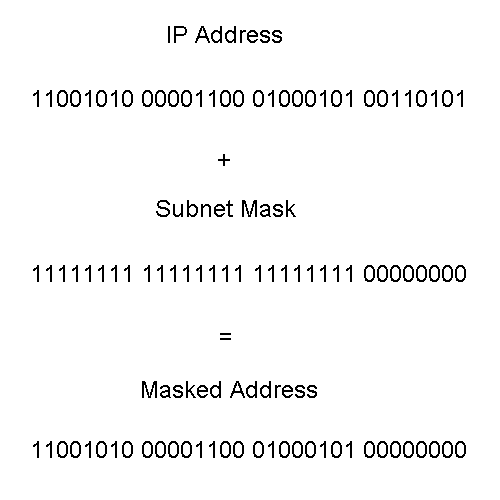
Figure 5 IP Address with Subnet Mask and Resulting Masked Address
Each 32-bit address is a pair that consists of the network ID and the host ID. The subnet mask is used to separate the network ID from the host ID. Notice in Figure 3-5 that the subnet mask is made up of complete octets of 1’s or 0’s. The 1’s are used to identify the network ID while the 0’s identify the host ID. The mask used in Figure 3-5 is the default mask for the corresponding IP address. The default masks will be examined in more detail in the next section of this chapter. If a mask other than the default mask had been used, then 1’s would have identified the network ID and also the subnetwork ID, while 0’s would have identified the host ID.
Almost every IP address belongs to a distinct class. These classes were defined by the Internet community to accommodate networks of various sizes. The class that the IP address belongs to initially determines the network ID and host ID portions of the address. The classes range from Class A to Class E; however, Microsoft TCP/IP supports only Classes A, B, and C addresses assigned to hosts. In this section we will examine each class of addresses.
Class A addresses are assigned to networks with a very large number of hosts. A Class A IP address has a 0 in the Most Significant Bit location of the first octet. The network ID is the first octet as shown in Figure 3-6.

Figure 6 Class A Network Address Breakdown
Class A addresses range from 0.1.0.0 to 126.0.0.0.
In the Class A range there is the possibility of having 126, networks with each network having the capability of 16,777,214 unique hosts when using the default subnet mask.
The default subnet mask for a Class A network is 255.0.0.0 or in binary representation 11111111 00000000 00000000 00000000.
Table 3-1 shows Class A IP addresses with various subnet masks.
Class A Address |
Subnet Mask |
End Result |
114.x.x.x |
255.0.0.0 |
16,777,214 hosts possible on the single network. |
114.x.x.x |
255.255.0.0 |
254 possible subnets with 65534 hosts for each subnet. |
108.x.x.x |
255.255.240.0 |
4094 possible subnets with 4094 hosts for each subnet. |
29.x.x.x |
255.255.255.128 |
131070 possible subnets with 126 hosts for each subnet. |
58.x.x.x |
255.248.0.0 |
30 possible subnets with 524286 hosts for each subnet. |
Table 1 Class A IP and Subnet Mask Examples
Class B addresses are assigned to medium-sized networks. A Class B IP address has a 1 0 in the two Most Significant Bit locations of the first octet. The network ID is the first and second octet as shown in Figure 3-7.

Figure 7 Class B Network Address Breakdown
Class B addresses range from 128.0.0.0 to 191.255.0.0.
In the Class B range there is the possibility of having 16,384 networks, with each network having the capability of 65,534 unique hosts when using the default subnet mask.
The default subnet mask for a Class B network is 255.255.0.0 or in binary representation 11111111 11111111 00000000 00000000.
Table 3-2 shows Class B IP addresses with various subnet masks.
Class B Address |
Subnet Mask |
End Result |
158.157.x.x |
255.255.0.0 |
65,534 hosts possible on the single network. |
142.13.x.x |
255.255.192.0 |
2 possible subnets with 16382 hosts per subnet. |
183.214.x.x |
255.255.255.0 |
254 possible subnets with 254 hosts per subnet. |
191.222.x.x |
255.255.255.252 |
16382 possible subnets with 2 hosts per subnet |
130.12.x.x |
255.255.248.0 |
30 possible subnets with 2046 hosts per subnet. |
Table 2 Class B IP and Subnet Mask Examples
Class C addresses are usually assigned to small Local Area Networks (LANs). A Class C IP address has a 1 1 0 in the three Most Significant Bit locations of the first octet. The network ID is comprised of the first three octets as shown in Figure 3-8.

Figure 8 Class C Network Address Breakdown
Class C addresses range from 192.0.1.0 to 223.255.255.0.
In the Class C range there is the possibility of having 2,097,152 networks, with each network having the capability of 254 unique hosts when using the default subnet mask.
The default subnet mask for a Class C network is 255.255.255.0 or in binary representation 11111111 11111111 11111111 00000000.
Table 3-3 shows Class C IP addresses with various subnet masks.
Class C Address |
Subnet Mask |
End Result |
198.157.21.x |
255.255.255.0 |
254 hosts possible on the single network. |
202.14.18.x |
255.255.255.248 |
30 possible subnets with 6 hosts per subnet. |
223.211.1.x |
255.255.255.192 |
2 possible subnets with 62 hosts per subnet. |
194.19.62.x |
255.255.255.252 |
62 possible subnets with 2 hosts per subnet. |
220.19.93.x |
255.255.255.224 |
6 possible subnets with 30 hosts per subnet. |
Table 3 Class C IP and Subnet Mask Examples
Class D addresses are used for multicasting to a number of different hosts. Data is passed to one, two, three, or more users on a network. Only those hosts registered for the multicast address will receive the data. A Class D IP address has a 1 1 1 0 in the four Most Significant Bit locations of the first octet. Figure 3-9 shows the layout of a Class D address.

Figure 9 Class D Network Address Breakdown
Class D addresses range from 224.0.0.0 to 239.255.255.255. There is the potential for having 268,435,456 unique multicast groups.
Currently Class D addresses are used mainly for experimentation. Membership in an IP multicast group is dynamic. A host can join or leave a group at any time they wish. You may see Class D addressing used for audio news multicasting, video presentations, or a music multicast.
Class E is an experimental address block that is reserved for future use. A Class E IP address has a 1 1 1 1 0 in the five Most Significant Bit locations of the first octet. Figure 3-10 shows the layout of a Class E address.

Figure 10 Class E Network Address Breakdown
Class E Ranges
Class E addresses range from 240.0.0.0 to 247.255.255.255.
There are some special Internet addresses that we need to discuss next You may wonder why a Class C address can have only 254 hosts and not 256 as it would seem, since an 8-bit number can have 256 different values. The reason for this is that two addresses are lost from the available host pool. The first is an address that has all 0’s in the host ID, which signifies "this host" and is normally used in a BOOTP process where a host doesn’t yet know its IP address. The second is an address that has all 1’s in the host ID which signifies a broadcast address. So, for example, in the Class C network 200.158.157.x , 200.158.157.0, and 200.158.157.255 are not available to hosts, which reduces the available number from 256 to 254.
If a network ID is all 1’s, it will be used for limited broadcasts. If the network ID is all 0’s, it signifies "this network." The number of Class A networks is reduced by one for this situation.
Network IDs cannot start with 127 because this address is reserved for loopback and is used mainly for testing TCP/IP and internal loopback functions on the local system. If a program uses the loopback address as a destination then the protocol software in the system returns the data without sending traffic across the network. 127 is technically a Class A address due to the high-order bit having a value of 0. But remember that 127 is reserved and not in use for live networks.
Table 3-4 consolidates the information on networks and hosts of the different classes we’ve discussed.
Class |
Networks |
Hosts |
A |
126 |
16,777,214 |
B |
16,384 |
65,534 |
C |
2,097,152 |
254 |
D |
--- |
--- |
E |
--- |
--- |
Table 4 Number of Networks and Hosts Per Class Address
In the previous sections we have examined the 32-bit IP address that is used to identify hosts on an internet. Data packets are sent and received using the 32-bit address. Ultimately, however, two machines on a physical network can communicate only if they know each other’s physical network address. In this section we will see how a host maps an IP address to the correct physical address.
If you are using a token ring network, resolution can be accomplished by direct mapping. With this type of network you have the capability of choosing both the IP and physical addresses that will be used. To make address resolution easy, you should select parts of both addresses that can be the same. For example, if you have a host with a Class C address of 204.121.27.62, then the network interface card (NIC) could be set for a physical address of 62 to match the host ID portion of the IP address.
On an Ethernet network each host has an Ethernet NIC that is encoded with a 48-bit physical address when the NIC is manufactured. Since it is impossible to fit a 48-bit address into a 32-bit address space, some other method of resolution needs tooccur. It is possible to manually maintain a table of mappings but this would be tedious and inefficient. A better method is to use a low-level protocol to dynamically bind addresses. In the next section we will examine this protocol.
In an Ethernet network the protocol used is appropriately named Address Resolution Protocol (ARP). ARP dynamically binds a high-level IP address to a low-level physical hardware address. ARP is used across a single physical network. For example, if host A needs to resolve the IP address for host B, then host A will broadcast a special packet to all hosts asking for host B to respond with its physical address. All the hosts will receive the special packet but they will disregard it, except for Host B. Host B will recognize its IP address and send back a response to host A that contains its physical address. After host A receives the reply, it will use the physical address to send the packet directly to host B. ARP is defined in RFC 826.
Windows NT comes with an ARP utility that can be used to view, add, or delete entries located in your ARP cache. The ARP cache is discussed in the next section of the chapter. Table 3-5 lists the commands available with the ARP utility. In conjunction with Table 5 here are definitions of a few of the common items you will see for each command:
| inet_addr - Specifies an IP address. | |
| eth_addr - Specifies a physical address. | |
| if_addr - If present, this specifies the IP address of the interface whose address translation table should be modified. If not present, the first applicable interface will be used. |
Command |
Purpose |
| ARP -s inet_addr eth_addr [if_addr] | The -s adds the host and associates the inet_addr with the eth_addr. The eth_addr is given as six hexidecimal bytes separated by hyphens. The entry is permanent. |
| ARP -d inet_addr [if_addr] | Deletes the host specified by inet_addr. |
| ARP -a [inet_addr] [-N if_addr] | Displays current ARP entries by interrogating the current protocol data. If inet_addr is specified, the IP and Physical addresses for only the specified computer are displayed. If more than one network interface uses ARP, entries for each ARP table are displayed. If the -N if_addr option is specified, then it displays the ARP entries for the network interface specified by if_addr. |
| ARP -g {inet_addr] [-N if_addr] | Same as ARP -a. |
Table 5 ARP Commands
When the requesting host receives the physical address from an ARP request, it saves both the IP address and the physical address as an entry in the ARP cache. All hosts maintain an ARP cache that includes their own IP address to physical address mapping. The ARP cache is always checked for an IP address to physical address mapping before initiating a broadcast.
Windows NT Server automatically adjusts the size of the ARP cache. Entries are dropped out of the ARP cache if they are not used by any outgoing data packets for two minutes. Entries that are being referenced get dropped out of the ARP cache after ten minutes. This type of entry is shown as dynamic under the Type heading. Entries added manually are never dropped out of the cache and are shown as static under the Type heading.
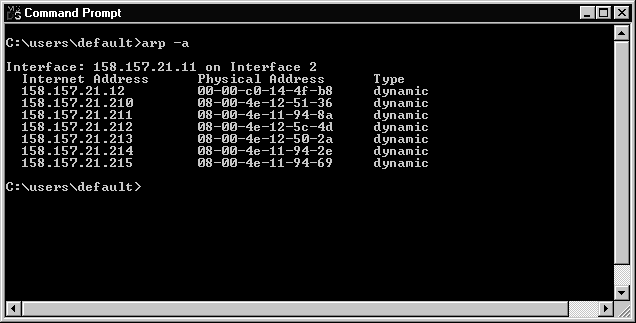
Figure 11 ARP Cache
It is possible for computers located on remote subnets, where DNS and WINS are not used, to use the HOSTS and LMHOSTS files to provide mappings for names to IP addresses. This name-resolution method was used on internetworks long before DNS and WINS were developed. The HOSTS file can be used as a local DNS replacement; and the LMHOSTS file can be used as a local WINS replacement.
Windows NT Server can be configured to search the HOSTS file to obtain mappings of remote host names to IP addresses. The HOSTS file format is the same as the format used for host tables in version 4.3 of the Berkeley Software Distribution (BSD) UNIX /etc/hosts file.
The HOSTS file is an ASCII file that can be modified with any text editor. An example of the HOSTS format is provided in the file named HOSTS in the Windows NT %systemroot%\System32\Drivers\Etc directory. You should edit the sample HOSTS file to include remote host names and IP addresses for each computer you will communicate with. Figure 3-12 shows an example of a HOSTS file.
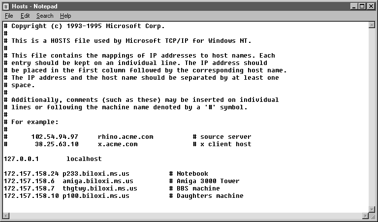
Figure 12 HOSTS File
The LMHOSTS file is an ASCII file that maps IP addresses to NetBIOS computer names. It contains entries for Windows-networking computers located outside the local subnet. The LMHOSTS file is read when broadcast name resolution or WINS fails. The resolved entries are stored in a local cache for later access.
Since LMHOSTS is an ASCII file, you can modify it using any text editor. An example of the LMHOSTS file is provided as a file named LMHOSTS.sam in the Windows NT %systemroot%\System32\Drivers\Etc directory.
Normally the LMHOSTS file is used for small-scale networks that do not have any servers available.
Figure 3-13 shows an example of the LMHOSTS file and Table3-6 defines all the keywords that can be used with the LMHOSTS file.
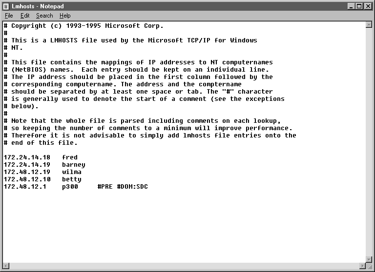
Figure 13 LMHOSTS File
Keyword |
Definition |
#PRE |
Defines which entries should initially be preloaded into the name cache. The entry is locked in the name cache and does not time out. |
#DOM:<domain name> |
Distinguishes a domain controller from non-domain controllers. This keyword is needed for all servers that validate logon requests. |
#NOFNR |
Avoid using Directed Name Queries (DNS). Some versions of LAN Manager cannot handle NetBIOS DNS requests and return an error. Specifying this flag on the same line will avoid using NetBIOS directed name queries. |
#BEGIN_ALTERNATE #END_ALTERNATE |
Defines a redundant list of alternate locations for LMHOSTS files. The recommended way to #INCLUDE remote files is to use a UNC path, to ensure access to the file. Be sure the UNC names exist in the LMHOSTS file with a proper IP address to NetBIOS name translation. |
#MH |
Associates a single, unique NetBios computer name to an IP address. You can create multiple entries for the same NetBios computer name for each NIC in the multihomed device, up to a maximum of 25 different IP addresses for the same name. |
#SG |
Defines a special group, such as printers or computers that belong to groups on the intranet for easy reference, browsing, or broadcasting. Special groups are limited to a total of 25 members. |
#INCLUDE |
Used with
#BEGIN_ALTERNATE and #END_ALTERNATE to define other locations for the LMHOSTS file. For example: #INCLUDE <\\server_name\sharename\LMHOSTS> |
Table 6 Keywords Available for the LMHOSTS File
The term gateway can have different meanings. A gateway can be used to connect two LANs that use different transport protocols or data formats; for example, connecting the IPX protocol to the IP protocol. In our discussion of TCP/IP, a gateway is simply a path for packets of data to be forwarded when there is no matching entry in the route table.
The default gateway is needed only for systems that are part of an internetwork. Data packets with a destination IP address not on the local subnet nor elsewhere in the route table are automatically forwarded to the default gateway. The default gateway is normally a computer system or router connected to the local subnet and other networks that knows the network IDs for other networks in the internetwork and the best path to reach them. Since the default gateway knows the network IDs of the other networks in the internetwork, it can forward the data packet to other gateways until the packet is ultimately delivered to a gateway connected to the intended destination. However, if the default gateway becomes unavailable, the system cannot communicate outside its own subnet except for systems it had established connections with prior to the failure.
If the default gateway becomes unavailable, data packets cannot reach their destination. Multiple gateways can be used to prevent this from happening.When a system is configured with multiple gateways, data transmission problems result in the system trying to use the other configured gateways, allowing internetworking communications capabilities tocontinue uninterrupted.
With the arrival of Windows NT Server 4.0 the default protocol that is initially installed has changed to TCP/IP. We will now learn how to configure each of the options that is available with this protocol.
The majority of Windows NT Servers probably have only a single NIC in them configured for only a single IP address, as shown in Figure 3-14. Later in this section we will discuss each of the options available for configuration.
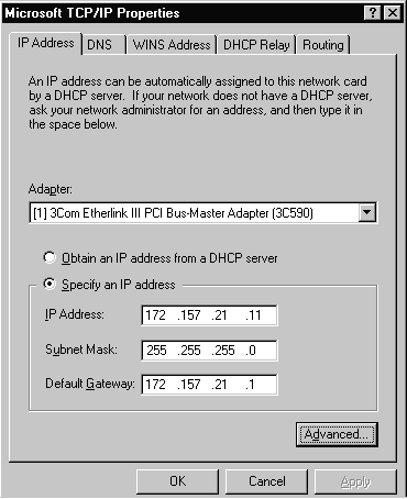
Figure 14 TCP/IP Properties Sheet of Single Adapter System
When a computer is configured with more than one IP address, it is referred to as a multi-homed system. You can multi-home your system in three different ways:
| Multiple IP addresses per NIC You can have several IP addresses bound to a single NIC. However, NetBios over TCP/IP (NetBT) binds only one IP address per NIC. When a NetBIOS name registration is sent out, only the first IP address listed in the network settings will be registered for each NIC. | |
| Multiple NICs per physical network You can have several NICS in your system that are on the same network and the only limitation is your hardware. | |
| Multiple networks and media types You can have several different networks supported by various media in your system. The main restrictions are hardware and media support. For example, you may have two different NICS in your system hooked to two separate networks. One may use fiber optics media and the other may use unshielded twisted pair cable. |
When an IP packet is sent from a multi-homed host, it will be given to the NIC with the most obvious route to the destination. The IP packet may display the source IP address of one NIC in the multi-homed host, yet be sent out by a different NIC. If this happens, then the source physical address on the packet will be that of the NIC that actually transmitted the packet onto the media.
You may encounter routing problems when a computer is multi-homed with NICs attached to separate networks. To work around this dilemma you may need to set up static routes to the remote networks.
Figure 3-15 shows one way to multi-home a system. It has two separate network interface cards configured for the system. Figure 3-16 shows the TCP/IP Properties Tab for the second NIC located in the system. As you can see, the IP address is different for each of the NICs.
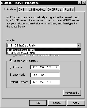
Figure 15 TCP/IP Properties Sheet for NIC #1 of Multi-Homed System
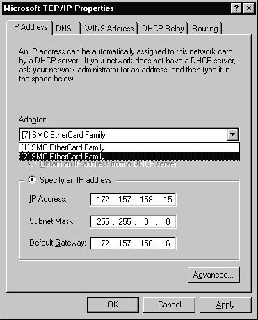
Figure 16 TCP/IP Properties Sheet for NIC #2 of Multi-Homed System
In this section we will examine each of the different tabs that is available for configuring TCP/IP on your system.
The first tab is the IP Address tab shown in Figure 3-16. On this tab you can specify an IP address or have one issued from the DHCP Server. Since we are talking about configuring a Windows NT Server I recommend that you give it a static IP address. Other selections on this tab are the subnet mask that is used on your network and the default gateway that will be used.
We mentioned earlier that there are several different ways to multi-home a system. If you select the Advanced button you will be presented with the option to add IP addresses to your NIC and also to specify additional gateways if necessary. Figure 3-17 shows the Advanced IP Addressing window in which two additional IP addresses have been bound to the NIC.
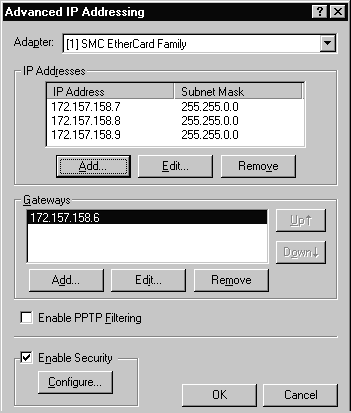
Figure 17 Advanced IP Addressing Window with Two Additional IP Addresses
It is also possible to enable Security and Point to Point Tunneling Protocol (PPTP)Filtering from this tab but they are optional and their use is dependent upon your particular situation. PPTP filtering is normally used only on a server that is used as a PPTP Server. By using the Security feature it is possible to restrict the ports and protocols that are permitted. Figure 3-18 shows the TCP/IP Security window.
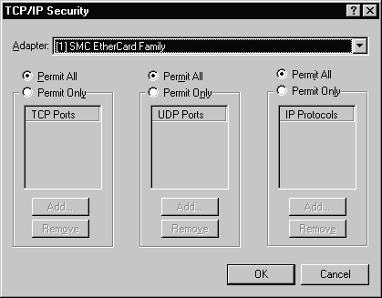
Figure 18 TCP/IP Security Window
The second tab is where DNS settings are configured, as shown in Figure 3-19. Refer to Figure 3-19 as we discuss the options.
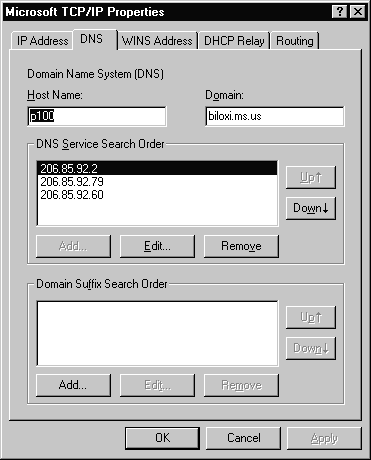
Figure 19 DNS Tab of the TCP/IP Properties
By default, this value is the Windows NT computer name, but it can be changed to another host name without affecting the computer name. For example, the host name cannot include an underscore even though the computer name may use an underscore in its name.
The domain is usually an organization name followed by a period and an extension that indicates the type of organization, such as nasa.gov. The domain is used with the host name to create a fully qualified domain name (FQDN) for the computer. The FQDN is the host name followed by a period (.) followed by the domain. For example, in the FQDN of p100.biloxi.ms.us, p100 is the host name and biloxi.ms.us is the domain. It is important to not confuse a DNS domain with a Windows NT domain. They are definitely different animals!
The Domain Suffix Search Order specifies the domain suffixes to be appended to host names during name resolution. You can change the search order of the domain suffixes by selecting a domain name to move, and then using the up and down arrow buttons.
The third tab is where information pertaining to WINS is configured, as shown in Figure 3-20.
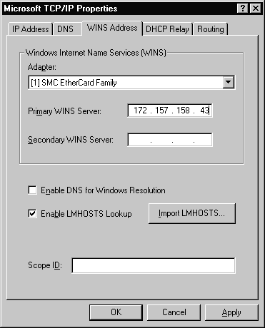
Figure 20 WINS Address Tab of the TCP/IP Properties
Refer to Figure 3-20 as we discuss the options.
It is possible to configure both a primary and a secondary WINS server for your system. If the primary WINS server cannot be reached for any function, then your system will request that function from its secondary WINS server. Periodically your system will attempt to switch back to its primary WINS server.
Select this box if you want to ensure that DNS servers will also be used in conjunction with the WINS servers to resolve client requests.
By default, the LMHOSTS lookup is enabled when TCP/IP is installed on your system. It is recommended that you do not disable LMHOSTS lookup because it provides a backup name service for WINS servers that are unavailable or off-line.
If you want to use an LMHOSTS file from a remote computer or different directory on your local system, click the Import LMHOSTS button and select the LMHOSTS file you want to use.
The fourth tab is where information for DHCP Relay is configured. This tab is used only if your system has had the DHCP Relay Agent service installed.
When a dynamic client system on the subnet where the DHCP Relay Agent resides requests an IP address, the request is forwarded to the subnet’s DHCP Relay Agent. The DHCP Relay Agent forwards the request directly to the correct system running the DHCP server service. The computer running the DHCP server service returns an IP address directly to the requesting client.
Figure 3-21 shows the DHCP Relay tab. Refer to Figure 3-21 as we discuss the options available.
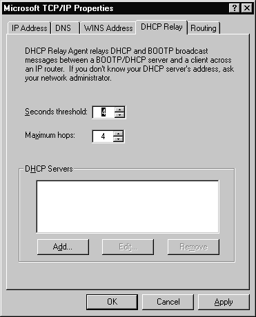
Figure 21 DHCP Relay Tab of the TCP/IP Properties
This option will limit the clients discover broadcast to the local subnet until the seconds threshold is reached. It can reduce network traffic and increase the chance that a local server will service the request.
The Relay Agent will forward the packet only if the seconds field is higher than the threshold set. RFC 1542 recommends the default to be 4 seconds. The seconds field is defined as the number of seconds from the first packet sent. For example, the first packet sent will have a value of 0. The next packet sent would have a value of 5, if it was sent 5 seconds after the first packet.
The maximum hops is the number of hops the DHCP Relay Agent will forward the request from the client.
This is where you type the IP address of the server that will provide the IP addresses to the requesting clients.
The fifth tab is where information for routing is configured. Figure 3-22 shows this tab and the single option that is available.
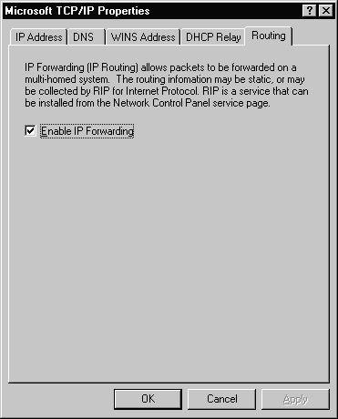
Figure 22 Routing Tab of the TCP/IP Properties
Enable IP Forwarding is the only option available on the Routing tab. It is used to allow IP packets to be forwarded between two NICs on a multi-homed system or to allow packets to be forwarded between Remote Access Service (RAS) and a NIC.
Now that you have seen the options available for configuring TCP/IP, it is your turn to practice. Exercise 3-1 will let you configure a Windows NT Server with multiple IP addresses.
Start Exercise
Exercise 3-1 Configure a Server with Multiple IP Addresses
End Exercise
Now that you have seen the options available for configuring TCP/IP on Windows NT Server, here is a quick reference for possible scenario questions relating to the configuration, and the appropriate answer:
Start Q &A
| "A multi-homed system has two network cards…" | Select Enable IP Forwarding in the Routing tab. |
| "The WINS servers are down and you cannot locate a machine on another network…" | Make sure that Enable LMHOSTS Lookup is selected on the WINS Server tab. |
| "You need to add several IP addresses to a single NIC…" | Select the Advanced button on the IP Address tab and add them from there. |
End Q & A
Now that you have configured TCP/IP on your system, you want to be sure that it will function correctly. Luckily there are several utilities available to help you. In this section we will examine two of them, IPCONFIG and PING.
If you are troubleshooting a system on a TCP/IP network, then you will need to know some basic information such as the IP address, subnet mask, and the default gateway. IPCONFIG is a command-line utility that can provide this information. Figure 3-23 shows the results after IPCONFIG has been executed on a system.
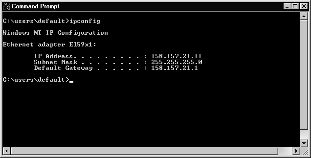
Figure 23 IPCONFIG Utility Running in DOS
It is always helpful to have as much information as possible. When IPCONFIG is used with the /all switch, it produces a very detailed configuration report for all interfaces in your system, including configured serial ports that are used for RAS. Figure 3-24 shows the results of using IPCONFIG /all on a system. Only the information for the first interface is displayed. The information for the second NIC and a serial port is not displayed. However, more information is displayed than when using the IPCONFIG command by itself.
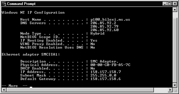
Figure 24 IPCONFIG /ALL Utility Running in DOS
Exercise 3-2 will give you the opportunity to trythe IPCONFIG utility.
Start Exercise
Exercise 3-2: Using IPCONFIG to Verify TCP/IP Configuration
End Exercise
The PING (Packet InterNet Groper) utility helps you to confirm IP-level connectivity. When you troubleshoot a TCP/IP problem, use the PING command to send an Internet Control Message Protocol (ICMP) echo request to a host name or IP address. I usually try to PING the IP address of the host to see if it will respond. If I am successful, then I try to PING the host name. PING uses Windows Sockets name resolution to resolve the name to an address. If I can PING the IP address but not the host name, then I know the problem is with the name resolution and not with network connectivity.
Figure 3-25 shows the output of the PING command and Table 3-7 lists the options that can be used with PING.
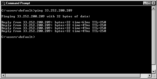
Figure 25 PING Utility Running in DOS
Option |
Purpose |
-t |
Ping the specified host until interrupted. |
-a |
Resolve addresses to hostnames. |
-n count |
Number of echo requests to send. |
-l size |
Send buffer size. |
-f |
Set Don’t Fragment flag in packet. |
-i TTL |
Time To Live. |
-v TOS |
Type Of Service. |
-r count |
Record route for count hops. |
-s count |
Timestamp for count hops. |
-j host-list |
Loose source route along host-list. |
-k host-list |
Strict source route along host-list. |
-w timeout |
Timeout in milliseconds to wait for each reply. |
Table 7 Options for the PING Utility
Exercise 3-3 lets you use the PING utility to verify IP connectivity to other systems.
Start Exercise
Exercise 3-3 Using PING to Connect to Other Servers
End Exercise
In order for a computer system to communicate on a TCP/IP network it must have a unique 32-bit IP address to identify itself. The 32-bit address consists of four 8-bit octets. The 32-bit address can be represented in binary format or as dotted decimal. Dotted decimal is easier for humans to remember. The IP address consists of a network ID and a host ID. The InterNIC is responsible for initially issuing network IDs for the Internet. The subnet mask is used to separate the network ID from the host ID.
There are five available classes of IP addresses. Class A addresses are for networks that have a great number of hosts. Class B addresses are for medium-sized networks. Class C addresses are usually for small LANs. Class D addresses are used for multicasting to a number of different hosts. Class E addresses are reserved for future use. There are special IP addresses that are used for broadcasts and loopback functions.
Address resolution is used to map the IP address to the physical address of a host. It can be done with direct mapping on token ring networks or by using ARP to dynamically bind the IP address to the physical address on an ethernet network. The ARP utility can be used to examine, update, and delete entries in your ARP cache. Entries in your ARP cache can be dynamic or static. Dynamic entries are purged from the ARP cache if they are not used within a certain time frame. Other methods of address resolution are to use either a HOSTS or LMHOSTS file.
Configuring TCP/IP on a Windows NT Server can be done on a system that uses a single NIC and a single IP address as well as on a system that uses multiple NICs or multiple IP addresses. Several choices need to be made when configuring TCP/IP, including whether you will be using a dynamic or static IP address, the subnet mask, and the default gateway. If you plan to use DNS, then there are several options that need to be configured, including the host name and the domain. WINS servers can be configured for each NIC that is in your system. If you have multiple NICs on a single network, then you need to enable IP forwarding.
Two utilities available to help you test your TCP/IP configuration are IPCONFIG and PING. IPCONFIG can provide a great deal of information about a systems configuration when used with the /all parameter. PING can help to isolate a network problem by sending ICMP echo requests to a host.
The following Self-Test questions will help you measure your understanding of the material presented in this chapter. Read all the choices carefully, as there may be more than one correct answer. Choose all correct answers for each question.
| The TCP/IP suite consists of several different protocols and the 32-bit address relates to the Internet Protocol (IP). | |
| An IP address uniquely identifies a system located on your network . | |
| The network ID is the portion of the 32-bit IP address that identifies which network a particular system is on. | |
| The host ID is the portion of the 32-bit address that identifies any device that has an IP address on your network. | |
| The subnet mask is a 32-bit value that distinguishes the network ID portion of the IP address from the host ID. | |
| Be careful when distinguishing the network ID and the host ID from the subnet mask. | |
| The classes of IP addresses range from Class A to Class E; however, Microsoft TCP/IP supports only Classes A, B, and C addresses assigned to hosts. | |
| Class A addresses are assigned to networks with a very large number of hosts. | |
| Class B addresses are assigned to medium-sized networks. | |
| Class C addresses are usually assigned to small Local Area Networks (LANs). | |
| Class D addresses are used for multicasting to a number of different hosts. | |
| Class E is an experimental address block that is reserved for future use. | |
| When calculating the number of networks or hosts that are available in a particular class, remember to account for special IP addresses that may be reserved for unique functions. | |
| If you are using a token ring network, resolution can be accomplished by direct mapping. | |
| ARP dynamically binds a high-level IP address to a low-level physical hardware address. | |
| It is possible for computers located on remote subnets, where DNS and WINS are not used, to use the HOSTS and LMHOSTS files to provide mappings for names to IP addresses. | |
| Know how HOSTS and LMHOSTS files are organized and what keywords are available, as well as their functions. | |
| A gateway can be used to connect two LANs that use different transport protocols or data formats. | |
| A gateway can also be a path for packets of data to be forwarded when there is no matching entry in the route table. | |
| With the arrival of Windows NT Server 4.0 the default protocol that is initially installed has changed to TCP/IP. | |
| When a computer is configured with more than one IP address, it is referred to as a multi-homed system. | |
| If you are troubleshooting a system on a TCP/IP network, then you will need to know some basic information such as the IP address, subnet mask, and the default gateway. IPCONFIG is a command-line utility that can provide this information. | |
| The PING (Packet InterNet Groper) utility helps you to confirm IP-level connectivity. Use the PING command to send an Internet Control Message Protocol (ICMP) echo request to a host name or IP address. |