| Using NT as a Router | |
| Understanding Routing | |
| Multihomed Hosts | |
| Static Versus Dynamic Routing | |
| Routing Tables | |
| ROUTE Command | |
| Routing Protocols | |
| Microsoft’s Implementation of Routing | |
| TRACERT Command |
In this chapter we will discuss the concepts of multihomed hosts containing more than one network interface, IP packet forwarding (also known as routing), and static and dynamic routing tables. Installation requirements to add dynamic routing to update routing tables automatically will be explained, as well as basic and advanced routing protocols: RIP, OSPF, and BGP. We will look at Microsoft’s implementation of routing and also examine the ROUTE and TRACERT utilities supplied with the TCP/IP software.
In addition to the basic networking software services on your NT operating system is a feature known as routing. Using a combination of software and hardware, routing gets a packet on one network to another network. An NT server with multiple network interface connections can act as a router between different networks of different protocols and media. The routing feature is provided for TCP/IP, AppleTalk, and IPX/SPX protocols. This section provides an overview of basic TCP/IP based routing; the terminology, features, required software components, and some benefits and drawbacks of these services.
If all machines could directly connect with every other machine, then each machine could simply keep a record of the IP address and intercommunication would be easy. Rarely can all machines be connected this way. More commonly, networks are broken up into related sets; by floor, building, office, corporate group, geographical region, or whatever you fancy. When the network is made up of many smaller networks, connections between them are handled by a host machine called a router, gateway, or bridge.
The term router is sometimes generically used to imply packet forwarding and protocol translation. Strictly speaking, this is a gateway, which is one step up from a pure router. A gateway provides router and protocol translation. Both a router and a gateway forward packets, also called datagrams, around a network; this is true routing. A bridge provides selective connection between LANs where only packets destined for the other side cross the bridge.
In the big picture of networks, there are small networks connected to large networks, which are in turn connected through backbone networks to each other. For instance, if the small networks are all the offices in each city, then the city is the large network. The backbone or core connections between the cities and other countries make up the entire network. The Internet was a major development ground for protocols to manage these networks.
Rather than having every router know about every other router, they are organized into interior and exterior, or small groups with borders and these borders are connected by the backbone.
Router Internet Protocol (RIP) is a common Interior Gateway Protocol (IGP) used by neighboring networks to communicate with each other. RIP messages are sent frequently to all adjacent routers from every other router providing basic route and hop information.
Interior Gateway Routing Protocol (IGRP) is a proprietary router-to-router intra-domain protocol developed by Cisco for their routers. This protocol has five metrics instead of just the one used in RIP, the hop count. These five metrics provide speed, delay, packet size, loading, and reliability information about routes and can be used to find "best" routes.
Gateway to Gateway Protocol (GGP) is used for traffic control between network cores. A core is a grouping of local subnets. The Exterior Gateway Protocol (EGP) is used between non-core machines. These protocols provide more detailed information about timing or vector distances. Each gateway needs to know about every other core gateway to compute the best route to a network, if there is more than one available.
Border Gateway Protocol (BGP) is an exterior gateway protocol that exchanges network reachability information only with other BGP routers, over a reliable transport layer connection and does not require periodic updates.
Knowledge about interior and exterior protocols is provided just for your information and is not critical to know for basic routing. In the Internet world of hundreds of thousands of routers and the resultant array of paths to every destination, the improved traffic flow provided by these protocols is well worth knowing about.
Any multihomed (multiple Network Interface Cards) NT machine can be configured as a router, not only for the same protocol, such as TCP/IP, but for other protocols as well, like IPX/SPX using RIP for IPX/SPX, or between topologies like Ethernet and Token Ring.
With two or more network interfaces, NT can transfer, and translate for the protocol or topology if necessary, packets received at one interface but destined for some other network reachable by one or more of the other interfaces. This is called routing. The protocol that is used to send a packet must provide some routing information within it. A packet is considered routable by the protocol used. TCP/IP and IPX/SPX are routable protocols. NetBEUI is not considered a routing protocol although some specialized, high performance, dedicated routers can forward NetBEUI packets. This is not recommended because it floods both networks with broadcast messages.
The postal system uses a similar concept to deliver letters. The address on an envelope or package (IP destination on a data packet) determines the letter’s destination. If the letter’s destination is local to the sender (same network, the Network Mask is used to determine this), then the sender can drop it off directly, in the same office, or locality (Local Area Network). If the address is not local, the letter is sent to the post office (the router), which then uses its internal forwarding system (routing table) to decide where next to send it (best or next route).
The postal code can be interpreted to represent what country, city, and street a letter is destined for. Similarly, the network number from an IP packet determines the remote area destination and whether to route or forward the packet to the destination.
Let’s look at the packet information when the destination address is on a remote network and see how IP does routing. Workstation 160.45.100.1 wants to send a packet to the destination host at 160.20.10.105.
The workstation checks the destination address with the ANDing process and determines that the packet needs to be routed. The workstation ARPs to the default gateway and receives the IP address of the gateway. It then addresses the packet with the newly obtained address.
Packet information:
Source hardware address 11 (created the packet)
Source IP address 160.45.100.1
Destination hardware address 5
Destination IP address 160.20.0.3
IP on the gateway inspects the destination address and says, "This isn’t for me." It then forwards the packet to network 160.20.
IP on network 160.20 uses ARP to obtain the hardware address for 160.20.10.105.
Receiving the hardware address, the packet is sent out with the newly obtained address.
Packet information:
Source hardware address 5 (created the packet)
Source IP address 160.45.100.1
Destination hardware address 13
Destination IP address 160.20.0.3
Once on the 160.20 network, the NIC recognizes itself and grabs the packet off the wire.
Looking at the packet information, you see that the hardware addresses are changing as the packet goes on its journey. The IP addresses are never changed.
— by D. Lynn White, MCT, MCSE
For a network protocol to be routable, the protocol software design must provide a mechanism for determining whether a packet is local or not. If it is not local, it is sent on to the router or gateway. The router is programmed to forward the packet like the post office would forward a letter through the postal system to the final destination.
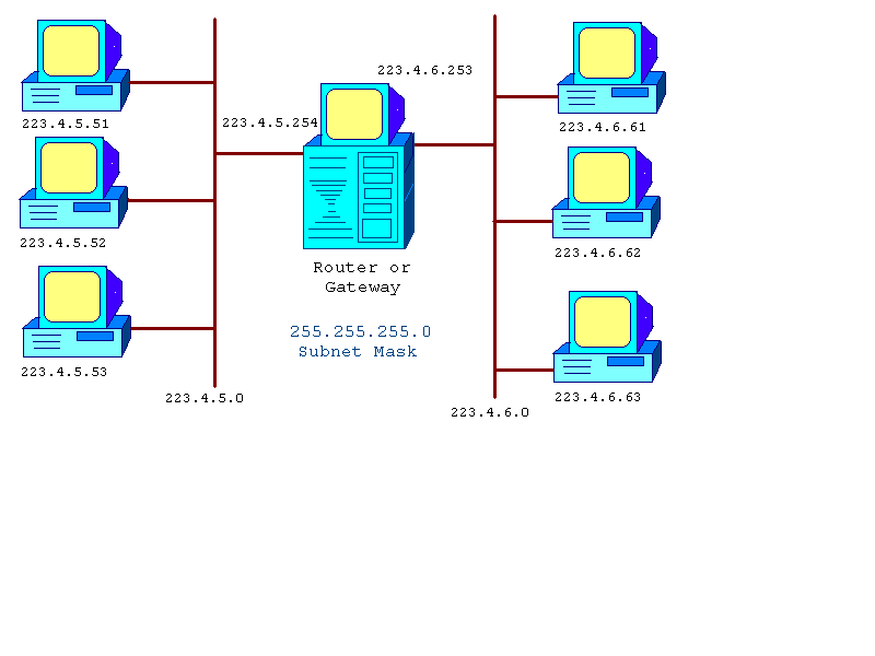
Figure 1 Subnetworks Connected by Router or Gateways
In Figure 5-1, the central host has two network cards, each with an address for their respective subnets. The left network is 223.4.5.0 and the right network is 223.4.6.0, based on the network mask of 255.255.255.0 used by both networks.
If the two network cards use different topologies, like Ethernet and Token Ring, then this is called a gateway. A gateway will translate the packets between these topologies.
To turn on the routing software, in the Network Applet of Control Panel, navigate through the Protocol Panel to TCP/IP Protocol Properties sheet's Routing Panel and click Enable Routing (see Figure 5-2):
START à Settings à Control Panel à Network à Protocols (Panel)
à TCP/IP à Properties à Routing (Panel)
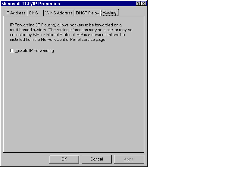
Figure 2 Enable Routing Panel in TCP/IP Properties Sheet.
For two small networks, as depicted in Figure 5-1, NT Routing can be efficient. For very large networks, where there are more than two networks being routed from the same point, dedicated routers are usually used, although, you could use an NT host instead of a router. Each routing NT server would require multiple network interface cards properly configured within them. As long as this was the only service that each routing server was providing or it was a multi-CPU host with lots of horsepower to spare, you would not see much of a performance difference compared to a dedicated router.
Dedicated routers are machines that provide only routing and translation services between networks and topologies. Additional services may include security and routing path optimization software such as Border Gateway Protocol (BGP),= or Open Shortest Path First (OSPF).
Most dedicated routers are not multiuser systems that provide file and print services like an NT server would;, for example, there is usually no monitor or keyboard attached. Terminal access to dedicated routers is usually via a telnet session across the network or from a dial-in port on the router itself. Some routers do have terminal ports, not video ports like a PC, but just the dumb terminal ports that support terminals with a VT100 or better display emulation. Some of the well known brand names for routers include Bay Networks, Cisco, Digital, Fore Systems, IBM, and Cabletron Systems.
These routers have their own built-in language for managing their features. They are dedicated to routing functions only and can be programmed for many different features along with advanced routing features. NT 4.0 provides a few of the many possible features available on these dedicated routers.
Mixing routing vendors usually means losing some of the functionality that is proprietary in nature to each manufacturer, Forcing you to use the lowest common denominator between them.
The term gateway is used to identify the network interface that can transfer or route a packet from one network to another network interface on another network.
In Figure 5-3, the central host has an interface on the 223.4.5.0 network with the IP address of 223.4.5.254. For each host on this network side to use the router, the TCP/IP setup would have to reflect this gateway address in its TCP/IP Protocol setup.
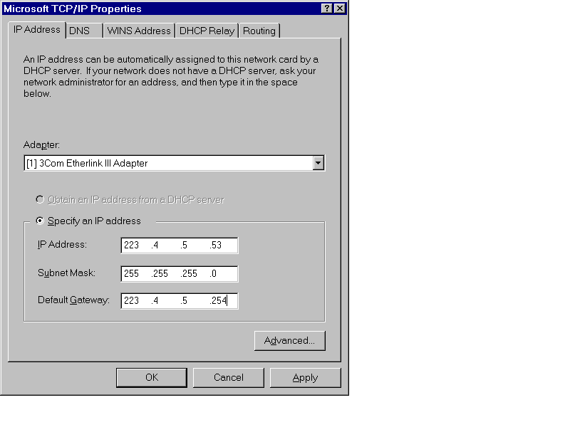
Figure 3 TCP/IP Setup for 223.4.5.53 Host to Use Gateway
Each client machine on the left side of the network would be configured similarly, with the same Network Mask and Default Gateway IP address:
Left Network
IP Network Mask Default Gateway
223.4.5.51 255.255.255.0 223.4.5.254
223.4.5.52 255.255.255.0 223.4.5.254
223.4.5.53 255.255.255.0 223.4.5.254
Each host on the right side network, 223.4.6.0, would have a similar setup except their Default Gateway would be 223.4.6.250, the interface on their network:
Right Network
IP Network Mask Default Gateway
223.4.6.61 255.255.255.0 223.4.6.253
223.4.6.62 255.255.255.0 223.4.6.253
223.4.6.63 255.255.255.0 223.4.6.253
The router ports would have a slightly different configuration; their default gateways would be each other.
When a packet from a left side host was destined for a right side host, then the network software on the host sending the packet would determine that it was a remote host and send it to the default gateway connection. This host would then route the packet onto the other network to the remote host. This action is also referred to as forwarding the packet.
Multihomed means there are two or more network interfaces on one machine. This is common on routers and switching equipment. Many Network Operating Systems using TCP/IP (NT 4.0, Novell, Banyan, UNIX, and others) also provide this routing service between network interfaces.
Each network card or modem connection has a network interface number specific to the network it is attached to as in Figure 5-3 above. Routing is the transferring of a packet from one LAN to another via a software program, the routing software.
Each network interface card gets an IP address specific to the network to which it is attached.
In Figure 5-3 above, the left side and the right side would be installed as follows:
IP Network Mask Default Gateway
Left Side
223.4.5.254 255.255.255.0 223.4.6.253
Right Side
223.4.6.253 255.255.255.0 223.4.5.254
The second network card acts as the default gateway for remote packets for the first network card and vice versa. The routing software then takes care of the actual packet transfer. In TPC/IP networks, the Network Mask is used to determine whether a packet should be routed. The packet is routed if the network number for the destination host does not match the network number of the local host.
Exercise 5-1 Installing and Configuring a Two-NIC Server as a Router
The two networks are 222.123.1.0 and 222.123.2.0 and the server has two correctly installed network interface cards, NIC's, (proper IRQ, RAM, and PORT as required). You will use a default Class C Network Mask. The first NIC will be 222.123.1.10 and will use the second NIC as its gateway, 222.123.2.20. NIC 2 will be similarly set up with the IP numbers reversed.
Please note: You must be logged on with administrator privileges to correctly install all services in any of these exercises.
IP Address: 222.123.1.10
Network Mask: 255.255.255.0
Gateway: 222.123.2.20
IP Address: 222.123.2.20
Network Mask: 255.255.255.0
Gateway: 222.123.1.10
You should now see the following configuration changes:
222.123.1.0 à 222.123.1.10
Server: 10NT20
222.123.2.20 ß 222.123.2.0
You could click Close if you are finished now or move on to the exercise to install RIP for Internet Protocol and then click on the Close button.
There is a special case of a single card acting as a router to two sets of networks that actually share the same local area cabling media.
In the case of the single network interface card you would have to have two distinct network IP addresses assigned to it, one for each network to be accessed. Static routes should be added to the interface so that packets from either network interface will use the other IP address on the same card as their default gateway. This is also known as a logically multihomed network interface.
There is a limit of five IP addresses for any one network adapter, to make the sys admin’s job manageable. Have you ever had to take two older machines with separate functions, like FTP and HTTP protocol servers, and integrate them onto one machine? The new machine can replace the two older machines and have both services appear as before, with independent IP addresses even though they are the same network card.
Additionally, you can assign alternate gateways to use if there are multiple routers providing routing to other networks. This provides failover should the primary gateway fail to forward the packet.
To add additional IP and/or gateway addresses to one network interface, click the Advanced option, lower right corner, on the IP Address panel of the TCP/IP Properties control window. Figure 5-4 shows the Advanced Options input control sheet.
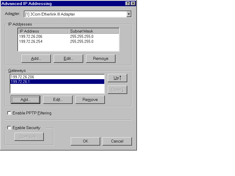
Figure 4 Advanced IP Options - Additional IP addresses and Gateway addresses on one Network Interface.
Only if your network has multiple gateways to access the remote networks and only if you need to have multiple IP addresses responded to by this machine, would you ever need to add these extra addresses. Simple installations will not need this, such as in the example network in Figure 5-1.
Early routers had to be programmed with exactly which networks they could route between which interfaces, especially if there were many network interfaces. This configuration method is called static routing. Pre-set routing tables are loaded from a disk file or EPROM into the router software at boot time or after any reset or reboot.
Dynamic routing requires additional software that sends special route information packets between routers. One of the early versions that is still used extensively is called the Routing Internet Protocol (RIP). NT provides this as a service you can add. (See the section on RIP in this chapter for more details.)
There are some newer routing information services called Border Gateway Protocol (BGP) and Open Shortest Path First (OSPF). They require router software that understands the packets and can use the information to determine the best, shortest, least cost, or alternate route to a remote network based on information passed back to the local router. You would need to add the Steelhead Routing upgrade to NT 4.0 to get this additional service.
Static routing refers to a specific table of routes input by you. This requires you as the router manager to manually configure the specific routing information for each interface. NT 4.0 is considered a static router until the addition of software to make it a dynamic router.
Each network card can be programmed with explicit routes to allow and or disallow specific routes. This gives the administrator explicit control over each interface. Additionally, you as the administrator can add the costs associated with routes as well as other related metrics to manage the flow of traffic between networks.
You can be very specific about the routing, filtering, and settings on every routing interface.
It is very difficult to corrupt from external sources and can be more secure than dynamic routing.
You must manually set up every interface and each interface will be different.
On large networks with many routers, gateways, and alternate routes, you also need to add information about metrics such as cost, which is a metric value you establish to compare route usage, to manage the flow of packets.
Dynamic routing protocols advertise the routes they are familiar with and pass on the metrics, number of other routers, or hops, required to get from their host to another network, either directly or indirectly through another router.
No further set up is required for all the interfaces, they learn from the other routers over time.
Dynamic routing generates continuous traffic from the routers with route update information.
They can be attacked from external sources with falsified RIP packets, which requires much more security and attention by a security officer, or you, for corruption and attacks.
They can create circle routes in complex networks with more than 16 hops.
With just two networks, the static routing setup is the most appropriate. In Figure 5-1, the routing interfaces have one static route and their default gateways are the other interface card. This is a basic static route. There are no other routes or options.
If your network has three or four parallel networks, as illustrated in Figure 5-5, then static routing may still be useful, although dynamic routing would be easier to set up.
However the actual setup is far more complex. You cannot simply have the routers route to the other network by assigning the gateway addresses to the other network interface card. This simply moves the packet to the other side when in actual fact the router needs to send the packet on to the specific gateway from that network to the next network.
In Figure 5-5, the network 223.4.5.0, Net5, needs to route 223.4.6.0, Net6, packets to 223.4.6.253. But packets for Net7 and Net8 from Net5 need to be sent to the next gateway, 223.4.6.252, so they can be forwarded on their way. Same goes for every other router interface. You must program each interface as to where to send packets from every other network.
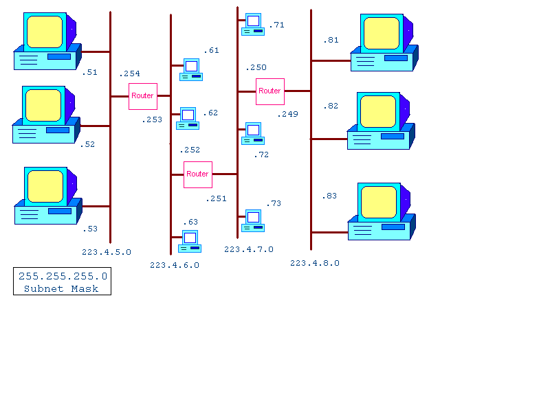
Figure 5 Four Networks with Routers
In Figure 5-5 the left-most network is numbered 223.4.5.0 and has hosts (223.4.5) .51, .52, and .53 plus the router interface .254 for a total of four interfaces. The right-most network also has four interfaces or nodes. The middle two networks have three hosts each and two router interfaces each.
Although the router is drawn as a single box, it may represent two servers with a dial-in connection using a modem from either side. The exact hardware is not important here, just the concepts first.
For the outside networks, 223.4.5.0 and 223.4.8.0, all clients are configured with their gateway pointing to the only router on their networks, 223.4.5.254 and 223.4.8.249, respectively. For these two outside networks, the router is their only gateway to all the other networks. A packet destined for any network other than the next one over requires that you program the router interface for a network one or two more hops away.
The middle two networks have a more interesting setup. They both have two router ports or gateways. You can program your client host machines with only one IP gateway address, so which do you pick? Does it matter? Either and maybe are the answers. You can pick either gateway and then program each gateway with static routes for the other remote gateways or pick the one most likely to be used most often. Secondly, it does not matter once proper additional routes have been added, although if the most heavily used gateway is selected, this will reduce the number of routers that will handle the packet.
Each independent router port has a routing table. In Figure 5-1 with the two networks only, the routing table would be a simple one with one entry for each card pointing to the other network interface as the gateway. This is a simplified description, as there are other routes which are not discussed in detail, such as references to internal interfaces, network, and broadcast addresses. Some of these are seen in Table 5-1.
In Figure 5-4, all three routers and their associated six ports would need to be programmed with the required static routes of the other networks if dynamic routing was not being used. You would want to make these permanent entries as well so that when the NT system is rebooted, the routes are re-established.
At the command prompt is a utility called ROUTE that is used to view and manage routes that are static and dynamic for an interface. You can delete and change dynamic routes but the next dynamic update may refresh the information.
At a command prompt if you have installed TCP/IP services, you can enter:
ROUTE To get help on all the commands
ROUTE PRINT To display the current routes configured
The default routes set up initially define some standard network numbers used internally and locally for test and broadcast.
Even on a basic network card interface there are numerous routes. Table 5-1 shows the output from a ROUTE PRINT command for a host with an IP address or 223.4.5.206.
C:\ > ROUTE PRINT
Active Routes:
Network Address Netmask Gateway Address Interface Metric
0.0.0.0 0.0.0.0 223.4.5.206 223.4.5.206 1
127.0.0.0 255.0.0.0 127.0.0.1 127.0.0.1 1
223.4.5.0 255.255.255.0 223.4.5.206 223.4.5.206 1
223.4.5.206 255.255.255.255 127.0.0.1 127.0.0.1 1
223.4.5.255 255.255.255.255 223.4.5.206 223.4.5.206 1
255.255.255.255 255.255.255.255 223.4.5.206 223.4.5.206 1
C: \ >
Table 1 Default Routes Created at Installation
In Table 5-1, the first route is for certain protocols like DHCP that use 0.0.0.0 as the host address initially. The third network is the local network. The last two routes are the broadcast address for the network and the general broadcast for the 0.0.0.0 network. All of these routes point to the local interface as their gateway.
The other network routes are internal routes that stop at the TCP/IP software itself. This is known as the loopback address and is usually 127.0.0.1 but it just has to start with 127; the rest of the numbers are not significant.
The broadcast address for every subnet is the network number combined with all the client bits being set to one, or the last address in the network range. The broadcast address is used by many protocols to send a general query to all machines on the network so that one or more of them may respond. For example, the Address Resolution Protocol (ARP) uses a broadcast to the network to locate the IP address of a local host.
IP (current version) addressing uses 32 bits conveniently broken into 4 octets, or 4 sets of 8 bits. A Network Number represents one combination of some of those 32 bits, from 2 minimum to 30 maximum. Generally, there are 3 well known groups called Class A, B, and C address ranges. The Class A addresses each have 24 bits that can be used for client numbers or over 16 million IP addresses; the network number in the first 8 bits does not change. The Class B network address is contained in the first 16 bits and the last 16 bits are used for client addresses, allowing for a total of 65,533 values. A Class C network address is in the first 24 bits and the last 8 bits are used for the client addresses.
Example of addresses in each basic class: (using default masks)
Class A 1-126 first octet value (127 reserved for Loopback)
12.33.234.23 255.0.0.0 12.0.0.0 Network 33.234.23 Client
58.38.94.123 255.0.0.0 58.0.0.0 Network 38.94.123 Client
Class B 128-191 first octet value
162.3.24.73 255.255.0.0 162.3.0.0 Network 24.73 Client
144.223.4.5 255.255.0.0 144.223.0.0 Network 4.5 Client
Class C 192- 223 first octet value
212.78.231.59 255.255.255.0 212.78.231.0 Network 59 Client
212.78.231.60 255.255.255.0 212.78.231.0 Network 60 Client
Classes D and E range from 224 to 254 in the first octet and are reserved for special uses.
In a Class A network, the 24 bits for the clients represent all the numbers between 1 and 2**24-1. The zero address, like 12.0.0.0, is reserved as the network number. The last address, where all the client bits are set to the value 1 is the broadcast address, 12.255.255.255.
The default mask is a number that identifies all the bits that represent the network number part of the IP address. For a Class A address, 255.0.0.0 is the default mask. This implies that all of the first 8 bits represent the network number. For a Class B address, the first 16 bits indicate the network number; the mask is 255.255.0.0 by default. For a Class C network, the first 24 bits define the network number and the mask is 255.255.255.0 by default.
Subnetting allows you to further break up a standard Class A, B, or C network into smaller sections. By using some of what are normally considered the client bits as part of the network mask, then you can subdivide larger groups into smaller groups of IP addresses.
You can subnet using all but the first bit and last 2 bits of the client addresses. The Class A addresses allow 2 to 22 bits, Class B allow 2 to 14 bits, and Class C allow 2 to 6 bits of the client bits to be used in subnetting the network.
If you use the first 3 bits from any Class A, B, or C network address and include this as part of the subnet, your network masks become:
| 255.224.0.0 for Class A | |
| 255.255.224.0 for Class B | |
| 255.255.255.224 for Class C |
The following section is a more complete example of subnetting various address classes using 2 bits. If you use the first 2 bits from any Class A, B, or C network address and include this as part of the subnet, your network masks become:
| 255.192.0.0 for Class A | |
| 255.255.192.0 for Class B | |
| 255.255.255.192 for Class C |
This creates 4 blocks from the original set of addresses for any class since the 2 bits have 4 possible combinations: 00, 01, 10, and 11. Unfortunately, you should not use any block that uses all zeros or all ones. This excludes the 00 and 11 address blocks. You end up with the 01 and 10 blocks or 2 subnets. The formula for the number of groups created is 2**n-2 (2 to the power of n less 2) where n is the number of bits used to create the subnets. This is summarized in Table 5-2.
Basic Class A Network has 2**24-2 clients (~16 million)
Network Using Netmask First Client Last Client Broadcast Address
12.0.0.0 255.0.0.0 12.0.0.1 12.255.255.254 12.255.255.255
Class A Network With 2 subnets of 2**22-2 clients (~4 million) each
12.64.0.0 255.192.0.0 12.64.0.1 12.127.255.254 12.127.255.255
12.128.0.0 255.192.0.0 12.128.0.1 12.191.255.254 12.191.255.255
Basic Class B Network has 2**16-2 clients (64K) clients
Network Using Netmask First Client Last Client Broadcast Address
162.2.0.0 255.255.0.0 162.2.0.1 162.2.255.254 162.2.255.255
Class B Network With 2 subnets of 2**14-2 clients (~16K) each
162.2.64.0 255.255.192.0 162.2.64.1 162.2.127.254 162.2.127.255
162.2.128.0 255.255.192.0 162.2.128.1 162.2.191.254 162.2.191.255
Basic Class C Network has 2**8-2 = 254 clients
Network Using Netmask First Client Last Client Broadcast Address
212.3.6.0 255.255.255.0 212.3.6.1 212.3.6.254 212.3.6.255
Class C Network With 2 subnets of 2**6-2 clients (62) clients each
212.3.6.64 255.255.255.192 212.3.6.65 212.3.6.126 212.3.6.127
212.3.6.192 255.255.255.192 212.3.6.129 212.3.6.190 212.3.6.191
Table 2 Subnet Client Addresses, Network Number, and Broadcast Addresses for Each Network Class.
The network broadcast address is the last address available for a given network; all client bits are set to the value 1. This address is used to send general query packets to all hosts on the network. Broadcast packets are used extensively in all network protocols to establish information about zero or more hosts. The broadcast address for each network in Table 5-26 is the right-most column for each network. Any packet using this address as the destination address forces every host on the network to interpret the request and reply if the request pertains to that host. This is similar to requesting a show of hands from everyone in a theater lineup who has a ticket. This would be considered a broadcast message that everyone listens to, whether or not they respond. For example,, a broadcast message might be to request the hardware address for a given host name.
There is one specialized network address that is reserved on every machine to represent the "software." This is called the local loopback address. On every machine, the Class A network 127.0.0.0 is used to represent the TCP/IP software. You can ping the loopback to test if your software is running. Normally the loopback is numbered 127.0.0.1 but any numbers after the 127. are acceptable, for example, 127.23.45.67. Just remember the octet numbers vary between 0 and 255.
Your local network is defined as all hosts using the same network number. In Table 5-2 the Class A network is 12.0.0.0 and all the local hosts are the IP addresses from 12.0.0.1 to 12.255.255.254. The broadcast address is the last address of this network, 12.255.255.255.
The assumption is that all host numbers for your local network are reachable directly; no gateway is needed. This defines a local area network. You could have 16 million connections on one Class A local area network but it would not be efficient. Nor would 64 thousand nodes on a Class B network be efficient, although you could try. You could not do this using one Ethernet segment as there is a limitation to number of nodes and overall wire length, but with enough bridges and repeaters, you might be able to do it.
Each machine is known to itself as the local host. This is just another host name for your machine that may appear in a HOSTS file, for instance. Every other host is considered a network host, some are local and some are remote, reached via another specialized machine offering IP forwarding services, also called routing.
To add a static entry, you need to know the network number of the remote network, the gateway address to the next network that can pass it on, or the gateway to the network itself.
In Figure 5-4, the router between the 223.4.5.0 and 223.4.6.0 has two ports. When a packet for the networks 223.4.7.0 or 223.4.8.0 arrives at either port, a static route should be added to forward the packet to the gateway address of the 223.4.7.0 network. The static routes to add would be for network 223.4.7.0 and network 223.4.8.0, both with network mask 255.255.255.0, to be sent to address 223.4.6.252. The port .252 would forward to its partner, 223.4.7.251, which would have a route to send packets bound for 223.4.8.0 to the router port 223.4.7.250. This router port, .250, would forward to port 223.4.8.249, which is on the correct network.
Part of the software provided with the NT TCP/IP package includes standard utilities like TELNET (client), FTP (client), PING, ARP, NETSTAT, NBTSTAT (Microsoft network specific), TRACERT (may be called traceroute on UNIX systems), and ROUTE.
The PING command is used to test connectivity and to provide timing information over a specific route. By default, the NT version of PING sends only four packets to the remote host and then quits. You can change this to continuous with the -T, continuous until CTRL-C, or '-N integer-value' options.
ARP is used to display the current ARP table, hardware MAC addresses where packets are to be sent for a given IP address. Note in Figure 5-6, that the MAC address for the remote site remains as the gateway address since this is where all local packets are sent to be forwarded. This is a good test to see if the packets are going to the right location.
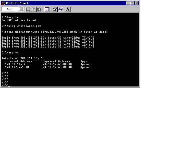
Figure 6 ARP and PING Commands
The ROUTE command can be used to add, modify, delete, and display route information for one or all interfaces. Enter the ROUTE command with no arguments to provide basic help instructions (see Figure 5-7). Figures 5-8 and 5-9 show the Print, Add Route, and Print Updated Table commands, all done at the DOS command-line.
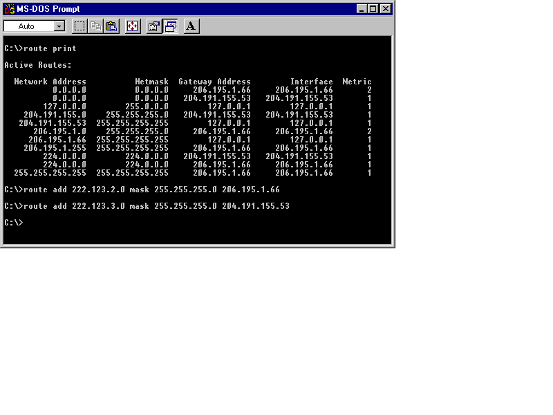
Figure 7 Entering the ROUTE Command at the DOS Prompt.
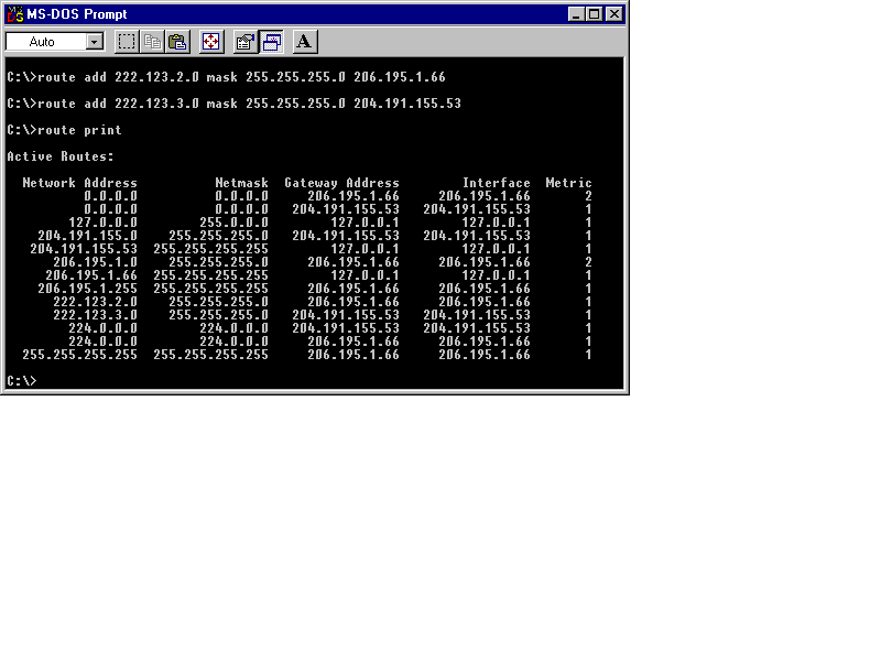
Figure 8 ROUTE Commands: Print and Add Route
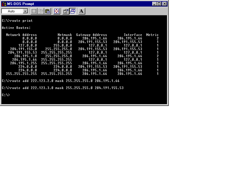
Figure 9 ROUTE Command: Print Updated Table
Normally, you would pipe the output from any command to MORE for page control (any key to see one more page or the end). But the help screen is actually written to error output. To save this information to a file and then view it:
C:\> ROUTE 2> ROUTE.TXT
C:\> TYPE ROUTE.TXT | MORE
You need to be at a command prompt to run the ROUTE command, there is no GUI based application (see Table 5-3 for a summary of ROUTE command arguments):
C:\ > ROUTE
Manipulates network routing tables.
ROUTE [-f] [command [destination] [MASK netmask] [gateway] [METRIC metric]]
-f Clears the routing tables of all gateway entries. If this is
used in conjunction with one of the commands, the tables are
cleared prior to running the command.
-p When used with the ADD command, makes a route persistent across
boots of the system. By default, routes are not preserved
when the system is restarted. When used with the PRINT command,
displays the list of registered persistent routes. Ignored for
all other commands, which always affect the appropriate
persistent routes.
command Specifies one of four commands
PRINT Prints a route
ADD Adds a route
DELETE Deletes a route
CHANGE Modifies an existing route
destination Specifies the host.
MASK If the MASK keyword is present, the next parameter is
interpreted as the netmask parameter.
netmask If provided, specifies a sub-net mask value to be
associated with this route entry. If not specified,
it defaults to 255.255.255.255.
gateway Specifies gateway.
METRIC specifies the metric/cost for the destination
All symbolic names used for destination are looked up in the network database
file NETWORKS. The symbolic names for gateway are looked up in the host name
database file HOSTS.
If the command is print or delete, wildcards may be used for the destination and gateway, or the gateway argument may be omitted.
Table 3 ROUTE Command Arguments
Exercise 5-2 Using ROUTE to View Routing Tables
In this exercise you will be adding a third network, 222.123.3.0, to the two networks used in the last exercise. The third network will be accessible via another port on your 222.123.2.0 network with IP address 222.123.2.254. You will add this route to the second network card.
222.123.1.0 à 222.123.1.10
Server: 10NT20
222.123.2.20 ß 222.123.2.0 à 222.123.2.252
Server: 20NT30
C:\> ROUTE PRINT
C:\> ROUTE ADD 222.123.3.0 MASK 255.255.255.0 222.123.2.252
C:\>
C:\> ROUTE PRINT
Where To Add Static Routes
The route commands needed at each interface are similar but all different. At each interface, you must program a route via a known gateway for all reachable networks.
Table 5-4 presents some example usage of the ROUTE command:
Show all routes
ROUTE PRINT
Add a permanent (stored in registry) route to a network via a gateway on the local net
ROUTE -P ADD 223.4.7.0 223.4.6.252
Change some parameter about a route
ROUTE CHANGE 223.4.7.0 MASK 255.255.255.0 223.4.6.252
Delete a permanent or not single route from the routing table
ROUTE DELETE 223.4.7.0
Delete all other routes and add one route to a gateway on the local net 2 hops away.
ROUTE -F ADD 223.4.7.0 223.4.6.252 METRIC 2
Table 4 ROUTE Examples
These are basic commands that must be entered at each interface. As you add networks to your intranet, you need to program each additional network at each interface. This is easy for two or three networks, but it can become very confusing as the network grows.
For a network of any size, there are easier methods. One of the most common is to use the dynamic routing protocol that has each router updating other routers about known paths so that you do not have to manually add each network route to every interface.
Exercise 5-3 Configuring Static Routing Entries
In this exercise, you will be adding a route from the first network for a fourth network beyond the third. In this case, the local gateway remains 222.123.2.252 for network 222.123.4.0.
222.123.1.0 à 222.123.1.10
Server: NT10RTR20
222.123.2.20 ß 222.123.2.0 à 222.123.2.252
Server: NT20RTR30
222.123.3.253 ß 222.123.3.0 à 222.123.3.30
Server: NT30RTR40
222.123.4.40 ß 222.123.4.0
C:\> ROUTE ADD 222.123.4.0 MASK 255.255.255.0 222.123.2.252
C:\> ROUTE PRINT
This route says that packets received at this address from any host on net 1 or 2 and destined for network 4 will be forwarded to the gateway address 222.123.2.252, which will then forward the packets on. This will require additional routing information at the port leading to network 3 and onward to network 4.
There are a several routing protocols, such as BGP and OSPF, but the original protocol is called Routing Internet Protocol (RIP) and is supported by NT 4.0 and most current dedicated routers.
RIP functions at two levels:
| Passive listens for route information and stores it. | |
| Active listens, stores, and sends its routing information on all subnets served by it. |
RIP provides the hop count, number of routers, or a cost value, assigned to provide more of a distance/speed vector than a pure hop count, to go through to get to a network. There is no real indication of speed or reliability.
A hop count of 1 indicates a direct connection; any other number indicates indirect paths. If a new route arrives with a similar hop count, it is ignored. A hop count of 16 means the network is unreachable.
Microsoft has put out an upgrade called Multi-Protocol Routing, also known as Steelhead. This provides DHCP Relay Agent, OSPF by Bay Networks and RIP Version 2 for Internet Protocol.
By installing the Multi-Protocol Router free upgrade from Microsoft, you can include the newer Version 2 of RIP as well as OSPF functionality if your network is large and could be improved with the additional functionality of groupings and backbones.
The RIP service, for each interface card, broadcasts the routes it can access as a general broadcast message type that RIP-enabled routers listen for and record in dynamic route tables.
It is a very well known standard packet protocol that provides single vector based hop/cost metric.
It is dynamic and no further configuration is needed.
RIP works on most other protocols and can pass information between them.
It provides basic information about known networks and a single metric about them.
RIP’s main advantages are that it is a very well known protocol that is supported by all known router manufacturers. Furthermore, it is easy to install and is self-configuring.
RIP’s disadvantages include the fact that it does not provide any information about flow, quality, speed, or congestion. Also no security information is given and it is not secure by nature.
RIP routes stalls when a critical member fails, and a slow convergence on the failed router can occur.
The Open Shortest Path First (OSPF) protocol is a link state protocol better suited for large complex networks with many routers. OSPF is an interior gateway protocol that distributes routing information between routers in a grouping called a single autonomous system (AS). OSPF chooses the least-cost path and can be programmed to send to more than one interface simultaneously.
Each router maintains a database describing the entire AS topology. OSPF datagrams are sent from all members, by flooding to all other members, to build this database.
Each multiaccess network with two or more attached routers has a designated router and backup routers. The designated router floods a link-state advertisement for the multiaccess network and has other specialized duties as well.
OSPF uses a multicast advertisement meant for other OSPF routers.
OSPF can also include authentication and can route onto multiple paths.
OSPF allows networks to be grouped into AS areas. Routes are then categorized into fur groups, in order of precedence:
| Intra-area Destinations within the same AS | |
| Inter-area Routes between AS areas |
Autonomous System External are routes to external destinations non-OSPF
| ASE Type 1 external Non-OSPF Routes with similar metrics to OSPF | |
| ASE Type 2 external Non-OSPF Routes with non-similar metrics |
OSPF uses the HELLO protocol to pass state information between gateways.
Each route provides local metric values about speed, traffic, and reliability as well as other information.
Its dynamic nature reduces administrative management required in large networks.
External route information can be determined from OSPF or EGP protocol information.
Large local area networks can be divided into smaller areas with their own gateway (border router) and routing algorithms separate from the backbone routing servers.
OSPF uses similar area and backbone terminology to the Internet but not exactly the same, which can cause confusion for administrators.
Another disadvantage is that it is not available on all routers.
To use it, you must establish SA borders and gateways.
OSPF requires significantly more memory for various tables at each router.
The route calculation is a more optimum path than the shortest path, based on known topology metrics.
RIP provides hop information, the number of machines between source and destination networks. This does not provide any physical or distance characteristics of the routes.
OSPF provides more advanced routing information to the routers themselves and can better manage large area network traffic patterns by breaking the networks into smaller groups with borders between them. OSPF can segment your network into larger groups that act as one AS, and then set up border machines that act much like a bridge between each of the AS areas. Table 5-5 summarizes the features of RIP and OSPF.
| RIP | OSPF |
| Vector Distance (Hops) | Link state - reliability, speed, etc. |
| No security | Authentication from a known source |
| Basic Masking | Variable masking - each area can use separate mask |
| Hop Count Routing | Type of Service Routing - selective based on state |
| Single Path - database per port | Multiple Paths - central database with many ports |
| No Choice other than hops | Load sharing based on link state values |
| Broadcast to all hosts | Multicast to OSPF hosts only |
Table 5 Features of RIP and OSPF
You can use RIP within a small segment of your network and then use OSPF for the larger network structure. They do not share any data and keep separate information at each router. This requires some maintenance but saves having to set up each of the smaller areas. The backbone and area border routers could be managed using OSPF and could thus be more reliable and secure, especially if connected to the Internet.
Microsoft TCP/IP services provide a very basic routing service that is static in nature; all additional routes must be manually added. During the year after the release of NT 4.0, Microsoft continued to improve the routing capability by updating to RIP version 2 and adding OSPF. This was called the Steelhead project and was released in late 1997 as Multi-Protocol Routing (MPR).
The base installation of TCP/IP and the subsequent selection of Enable IP Routing on the Routing panel of the TCP/IP properties sheet provides static routing only. This means additional routing information must be entered manually.
If you want dynamic RIP routing to be enabled, you must also install the additional RIP for Internet Protocol service. Only RIP Version 1 service is provided with the standard NT 4.0 installation files. If you want to upgrade to RIP Version 2 and or OSPF, you will need to download the Multi-Protocol Router software from Microsoft's Web site:
http://www.microsoft.com
The Routing Internet Protocol advertises known local routes with a hop count of 1 and adjacent routes obtained from other routers with a hop count incremented by 1 to the other gateways.
You must add the RIP for Internet Protocol service to your network services if you want dynamic RIP services.
Exercise 5-4 Installing the RIP for Internet Protocol Service
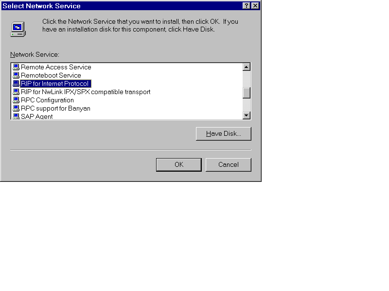
Figure 10 Routing Property Page
To configure basic static routing on a multihomed NT computer, you need to have two or more network interface cards, NIC's, installed and configured correctly along with the TCP/IP protocol. Each NIC will then get a unique address on the attached network, the proper network nask for the network, and the gateway address will point to the address of the other NIC in the machine in both cases. You must then Enable IP Forwarding on the Routing panel of TCP/IP Properties. This will provide static routing.
To upgrade to full dynamic routing, install the RIP for Internet Protocol service as we did in Exercise 5-4. No further configuration is required.
Another useful utility supplied with the TCP/IP software is the TRACERT utility used to trace a route from origin to destination. Each router interface encountered is echoed to the screen along with some statistical information about the path timing.
The actual mechanism used by TRACERT is to send a series of sequentially marked packets destined for the remote location with the Time-To-Live, TTL, setting started off at 1 and incremented by 1 after each interface returns an Internet Communication Message Protocol, ICMP, (in other words, a reply). A known control for network floods was the TTL value. Every interface that handles a packet decrements the TTL value by 1. This ensures the packet does not continue on forever in some unknown loop. The receiving host returns an error message, via ICMP, because the TTL value is zero at this interface. Table 5-6 lists the TRACERT commands available.
Usage: tracert [-d] [-h maximum_hops] [-j host-list] [-w timeout] target_name
Options:
-d Do not resolve addresses to hostnames.
-h maximum_hops Maximum number of hops to search for target.
-j host-list Loose source route along host-list.
-w timeout Wait timeout milliseconds for each reply.
Table 6 TRACERT Command and Arguments
The TRACERT command can very useful in determining serviceability of a route since the output includes three average timing values. The comparison of these values from time to time can indicate the congestion, reliability and if alternate routes are ever used.
Sometimes a route becomes congested or unreachable and the TRACERT command can show this as well as retry the request a number of times just in case as seen in Figure 5-11. Figure 5-12 shows a successful (completed) connection to a host.
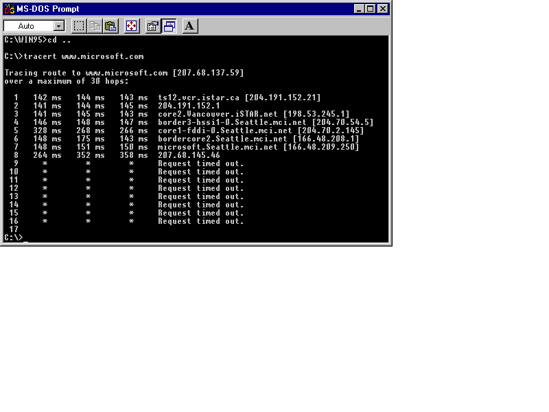
Figure 11 TRACERT: Unreachable Routes Are Retried Multiple Times before Failure.
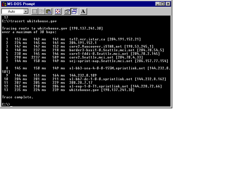
Figure 12 TRACERT: Completed Connection to Whitehouse.gov Host.
Exercise 5-5 Using TRACERT to Follow a Message Through Its Route
In this exercise you will trace the route taken to get to the third network from the first. You should do this from a client and not the routing server. Select a client in the first network like 222.123.1.15. You can ping the gateway port on the third network, 222.123.3.30.
C:\> TRACERT 222.123.3.30
Exercise 5-6 Configuring 3 Routers Between 4 Networks
In this exercise you will complete the routing requirements for all gateways to support all other networks. Each gateway interface must know to which next gateway interface a packet must go if it is not local to that interface.
The end result looks something like this:
Network à Gateway IP
222.123.1.0 à 222.123.1.10
route Add 222.123.2.0 MASK 255.255.255.0 222.123.2.20
route Add 222.123.3.0 MASK 255.255.255.0 222.123.2.20
route Add 222.123.4.0 MASK 255.255.255.0 222.123.2.20 metric 2
222.123.1.10
Server: NT10RTR20
222.123.2.20
route Add 222.123.1.0 MASK 255.255.255.0 222.123.1.10
route Add 222.123.3.0 MASK 255.255.255.0 222.123.2.252
route Add 222.123.4.0 MASK 255.255.255.0 222.123.2.252
Gateway IP ß Network à Gateway IP
222.123.2.20 ß 222.123.2.0 à 222.123.2.252
route Add 222.123.1.0 MASK 255.255.255.0 222.123.2.20
route Add 222.123.3.0 MASK 255.255.255.0 222.123.3.30
route Add 222.123.4.0 MASK 255.255.255.0 222.123.3.30
222.123.2.252
Server: NT20RTR30
222.123.3.30
route Add 222.123.1.0 MASK 255.255.255.0 222.123.2.252
route Add 222.123.2.0 MASK 255.255.255.0 222.123.2.252
route Add 222.123.4.0 MASK 255.255.255.0 222.123.3.253
Gateway IP ß Network à Gateway IP
222.123.3.253 ß 222.123.3.0 à 222.123.3.30
route Add 222.123.1.0 MASK 255.255.255.0 222.123.3.30 metric 2
route Add 222.123.2.0 MASK 255.255.255.0 222.123.3.30
route Add 222.123.4.0 MASK 255.255.255.0 222.123.4.40
222.123.3.253
Server: NT30RTR40
222.123.4.40
route Add 222.123.1.0 MASK 255.255.255.0 222.123.3.253 metric 3
route Add 222.123.2.0 MASK 255.255.255.0 222.123.3.253
route Add 222.123.3.0 MASK 255.255.255.0 222.123.3.253
Network à Gateway IP
222.123.4.0 à 222.123.4.40
This chapter has introduced you to the concepts of multihomed hosts containing more than one network interface, either network cards or modem connections; the concept of IP packet forwarding, also known as routing, explained for simple and complex networks; and static and dynamic routing tables. We learned the installation requirements to add dynamic routing to update routing tables automatically. We discussed basic and advanced routing protocols: RIP, OSPF, and BGP. Finally, we looked at Microsoft’s implementation of routing, which is static by default. We learned how to add RIP for Internet service to provide dynamic routing, or multiprotocol routing, Steelhead. We examined the ROUTE and TRACERT utilities supplied with the TCP/IP software for management and information.
| Using a combination of software and hardware, routing gets a packet on one network to another network. | |
| The term router is sometimes generically used to imply packet forwarding and protocol translation. | |
| A gateway provides router and protocol translation. | |
| Both a router and a gateway forward packets, also called datagrams, around a network; this is true routing. | |
| A bridge provides selective connection between LANs where only packets destined for the other side cross the bridge. | |
| Router Internet Protocol (RIP) is a common Interior Gateway Protocol (IGP) used by neighboring networks to communicate with each other. | |
| Gateway to Gateway Protocol (GGP) is used for traffic control between network cores. | |
| A core is a grouping of local subnets. | |
| Any multihomed (multiple Network Interface Cards) NT machine can be configured as a router, not only for the same protocol, such as TCP/IP, but for other protocols as well, like IPX/SPX using RIP for IPX/SPX, or between topologies like Ethernet and Token Ring. | |
| The central host in Figure 5-1 must have routing turned on and their respective gateway addresses must point to the other network card for routing to work. | |
| Gateways are routers that can also translate the packet format between topologies. For instance, a Token Ring NIC and an Ethernet NIC would require packet translation to the different formats. Pure routers simply use software to forward a packet between interfaces. | |
| Enable IP Forwarding is the term used to enable routing in NT TCP/IP. | |
| Multhomed means multiple network interfaces. | |
| Routing requires two or more network interface cards, including a modem acting as a network interface. | |
| Network setups are completely up to the individual administrators. Some administrators like to use the last few addresses for their router connections, as shown here, and some like to use the first few addresses for routers and possibly servers. It makes no difference technically. Microsoft course materials commonly uses low number assignments for their router IP addresses but there is no required standard. | |
| Early routers had to be programmed with exactly which networks they could route between which interfaces, especially if there were many network interfaces. This configuration method is called static routing. | |
| Dynamic routing requires additional software that sends special route information packets between routers. | |
| Each independent router port has a routing table. | |
| IP addresses use 8-bit numbers and can never exceed the value 255. | |
| The ROUTE command can be used to add, modify, delete, and display route information for one or all interfaces. | |
| There are a several routing protocols, such as BGP and OSPF, but the original protocol is called Routing Internet Protocol (RIP) and is supported by NT 4.0 and most current dedicated routers. | |
| Another useful utility supplied with the TCP/IP software is the TRACERT utility used to trace a route from origin to destination. |